Webber Electro Corp

FIRST-PRINCIPLE DESIGN

Safety is a system, not a checklist.

Battery control architectures designed around real operating conditions, not ideal laboratory assumptions.

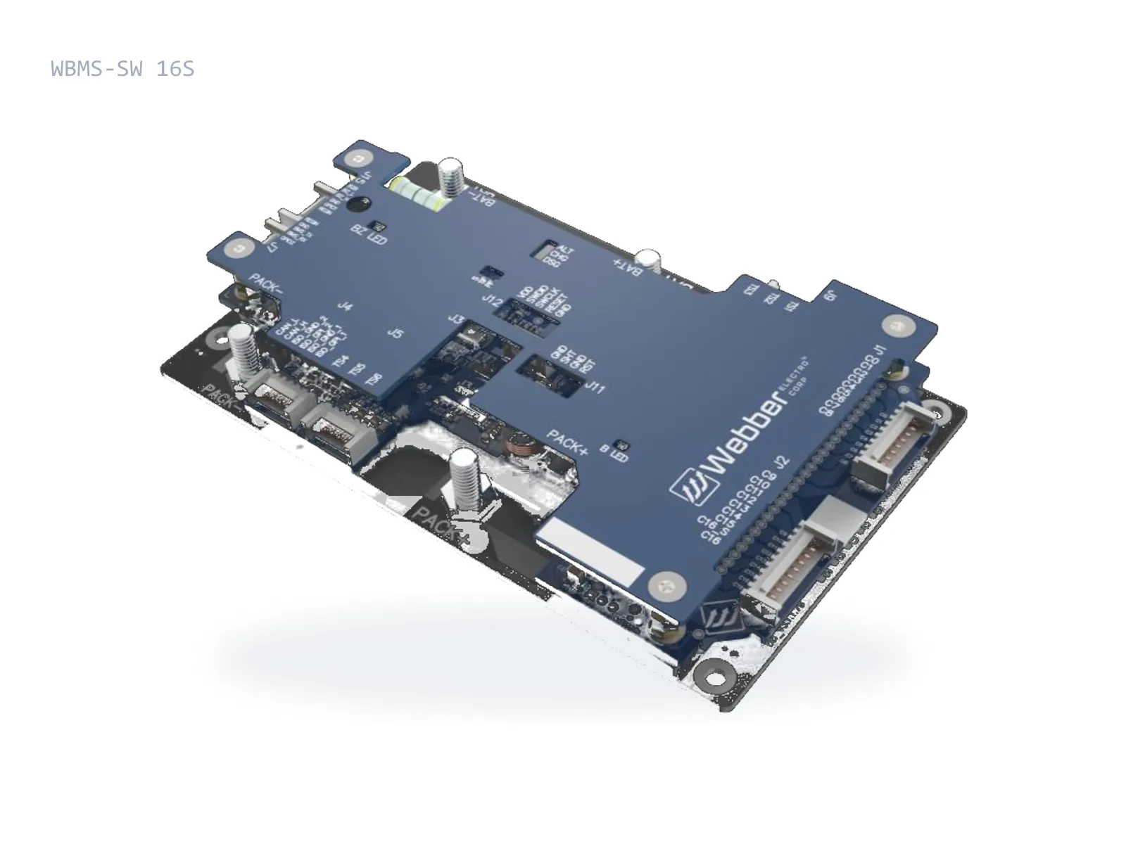
Assembled Webber battery management boardTAP TO EXPLODE
  1. 1COMPONENT LAYER
  2. 2COPPER CIRCUIT
  3. 3DIELECTRIC
  4. 4ALUMINIUM METAL CORE

SYSTEM ARCHITECTURE

From cell measurement to fleet decision.

  1. CELLS

    16S to 32S packs, 12V to 1200V systems.

  2. SENSING

    Cell voltage, pack current and temperature channels.

  3. DECISION LAYER/ WEBBER

    State of charge and power, charging control, fault logic.

  4. PROTECTION + BALANCING/ WEBBER

    Over/under voltage, over-current, short circuit, open wire. Up to 400 mA balancing.

  5. VEHICLE / STORAGE CONTROLLER

    Isolated CAN across the low- to high-voltage boundary.

01 / BATTERY PARALLELING

Paralleling without CAN dependency.

THE PROBLEM
Swappable packs can have meaningful state-of-charge differences.
THE APPROACH
A proprietary paralleling architecture that does not depend on inter-pack CAN communication.
THE SYSTEM ADVANTAGE
Simpler swapping architecture and uninterrupted power delivery.

Proprietary architecture
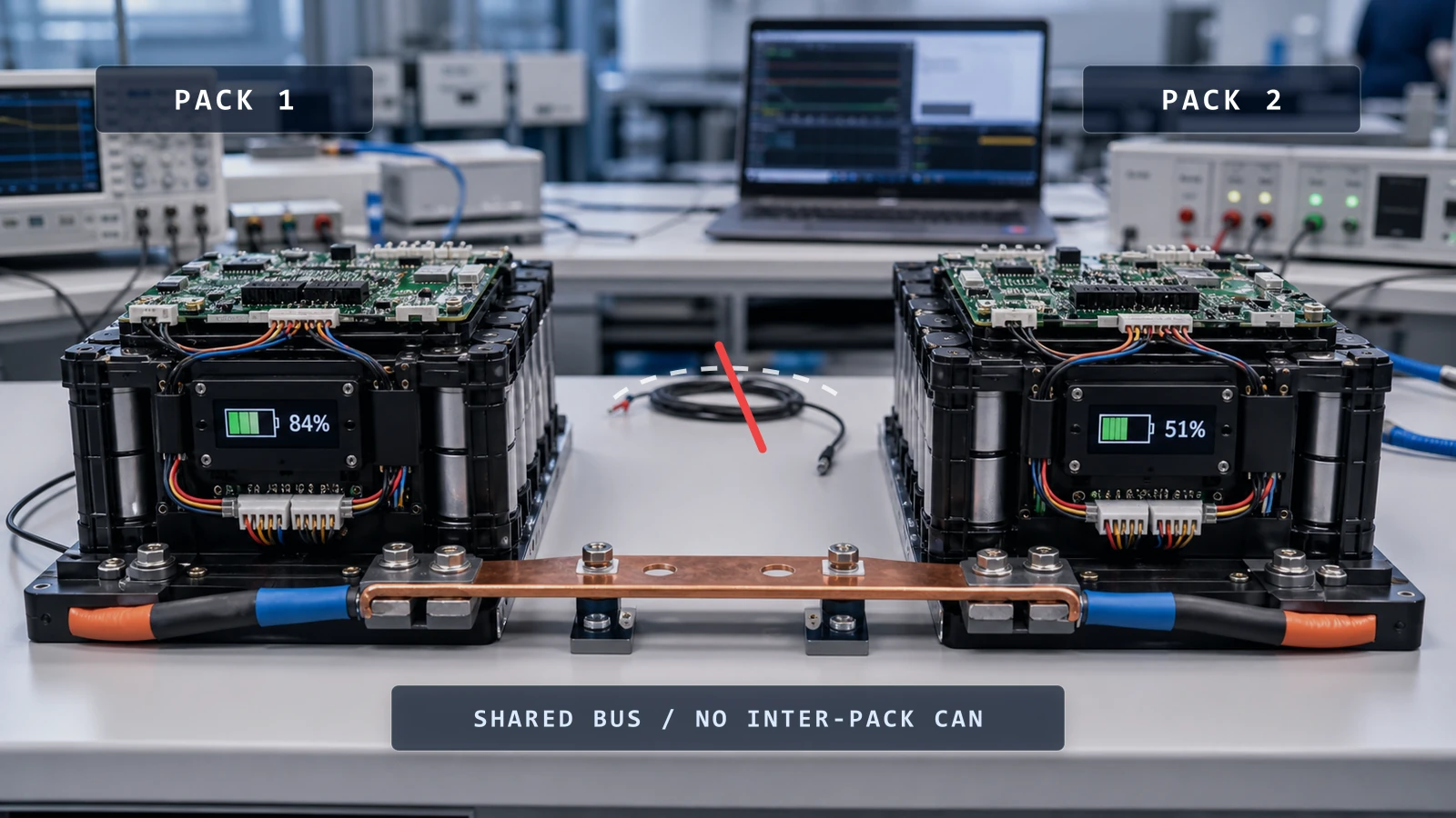
Two battery packs connected through a shared power bus with no inter-pack CAN connection

02 / CHARGING CONTROL

Charge with the cell state, not only the pack voltage.

THE PROBLEM
Voltage-only charging leaves capacity on the table and stresses outlier cells.
THE APPROACH
Enhanced charging algorithms with charging-profile control and balancing interventions during charge.
THE SYSTEM ADVANTAGE
Enhanced usable capacity: the pack actually reaches full charge.

Proprietary algorithm

CELL-STATE CONTROLPACK-VOLTAGE ONLYCHARGE TIME →

03 / HIGH-CURRENT BALANCING

Faster cell equilibrium. More usable pack performance.

THE PROBLEM
Low balancing currents leave large packs permanently out of equilibrium.
THE APPROACH
Industry-leading balancing current (up to 400 mA) with dedicated balancing algorithms.
THE SYSTEM ADVANTAGE
Faster equilibrium across the pack and more usable capacity per cycle.

Proprietary method

BEFOREAFTER / 400 mA BALANCING

04 / METAL-CORE THERMAL ARCHITECTURE

Heat moves through the design, not into the failure mode.

THE PROBLEM
High-current BMS hardware concentrates heat into MOSFETs and shunts.
THE APPROACH
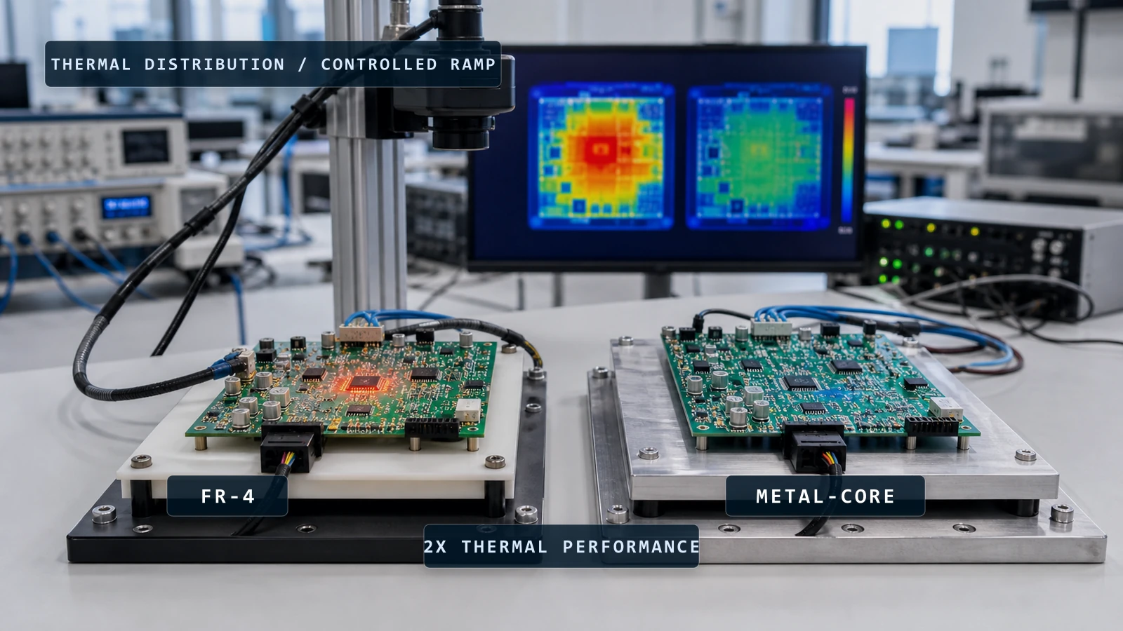
Metal-core PCB construction that spreads and extracts heat structurally.
THE SYSTEM ADVANTAGE
2× better thermal performance and extended peak performance under sustained load.

Patented

Thermal bench comparison: an FR-4 board running hot beside a cooler metal-core board, with both thermal maps on the camera monitor

05 / ISOLATION + MONITORING

High-voltage aware by design.

THE PROBLEM
High-voltage systems fail unsafely when isolation is an afterthought.
THE APPROACH
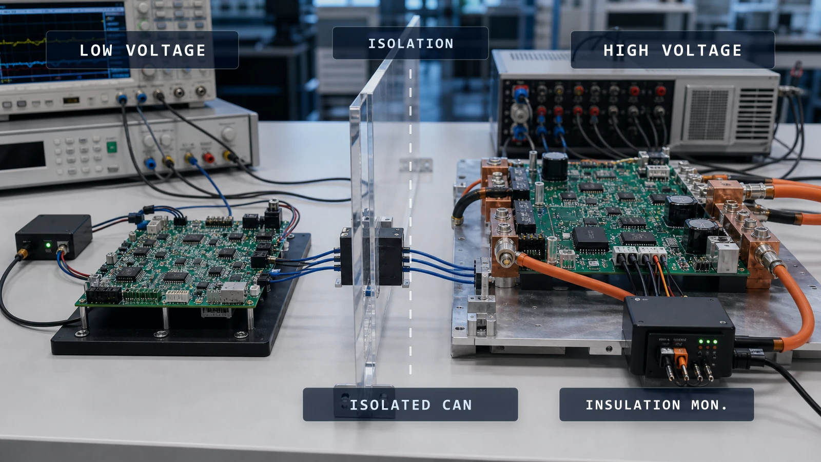
Insulation monitoring, isolated CAN communication and clear low-voltage/high-voltage boundaries.
THE SYSTEM ADVANTAGE
Industry-first isolation features with temperature-based early detection of thermal runaway.

Industry-first feature set

Low-voltage and high-voltage BMS domains separated by an isolation barrier with isolated CAN and insulation monitoring

COMPLIANCE

Engineered for certification.
Validated for deployment.

AIS 156 / PHASE 2

WBMS-SW 16S/24S certified variants

Applicable variants
WBMS-SW 16S / 24S (certified configuration)
Functional scope
µSD card and buzzer integration per AIS 156 PH-2
Test laboratory
Certificate reference

VALIDATION

Designed at the bench.
Proven in the field.

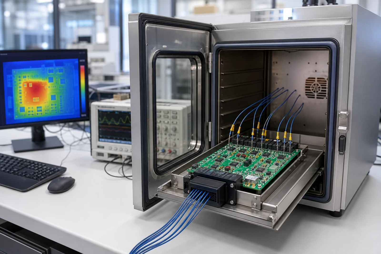
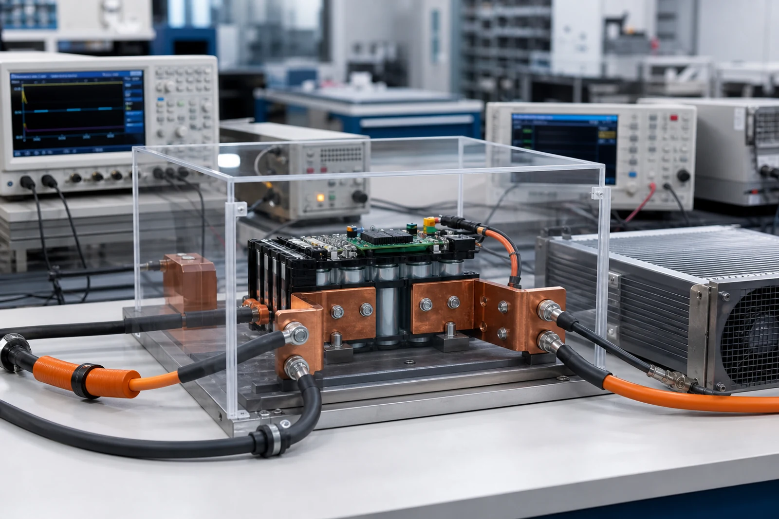
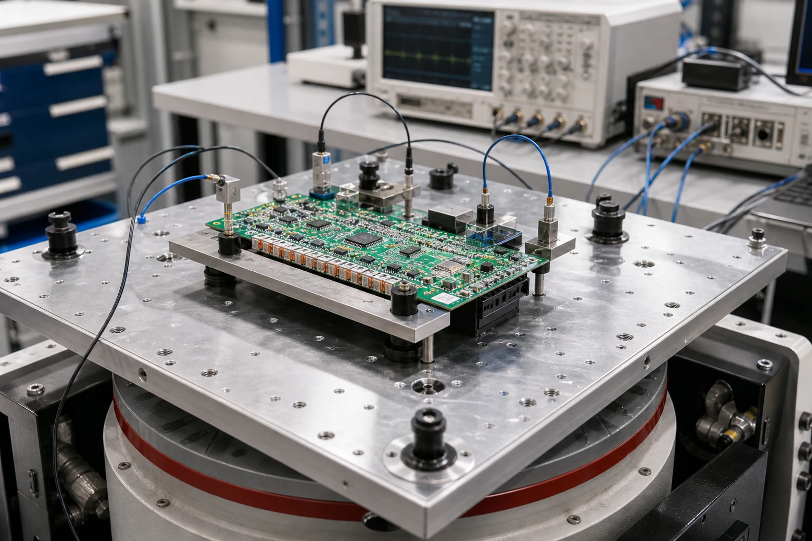
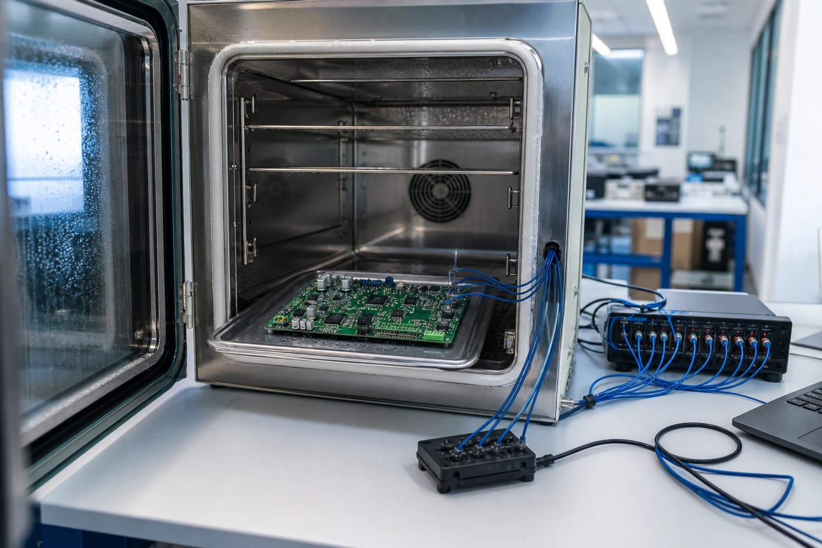
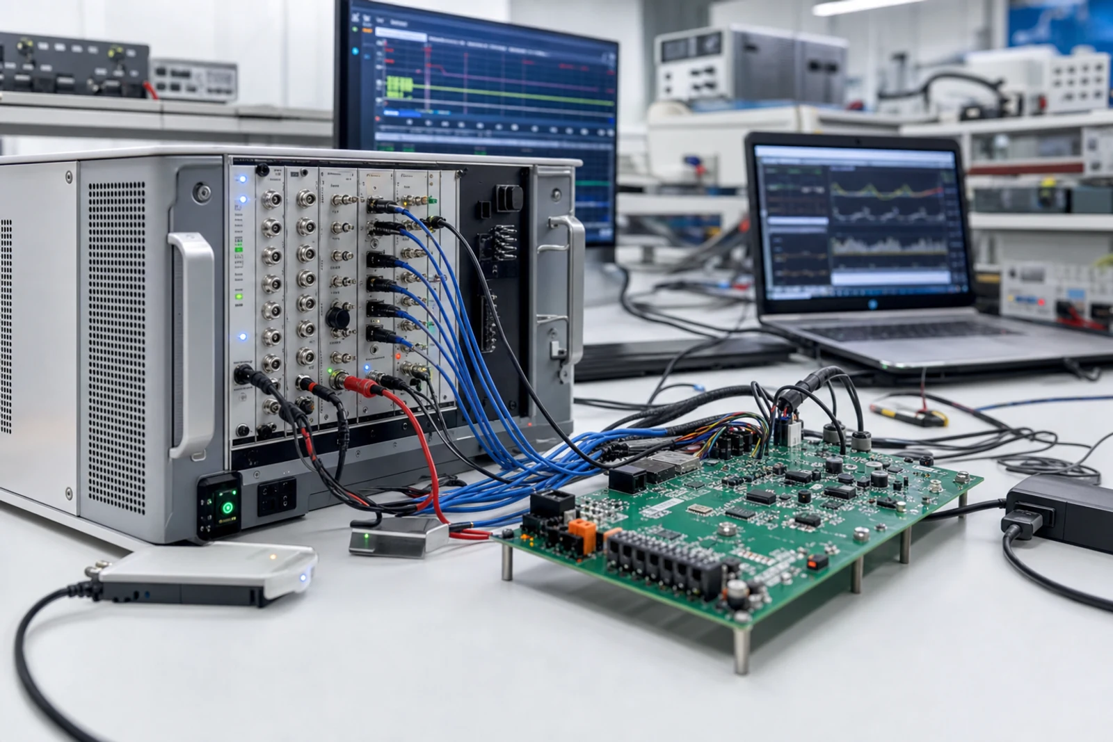
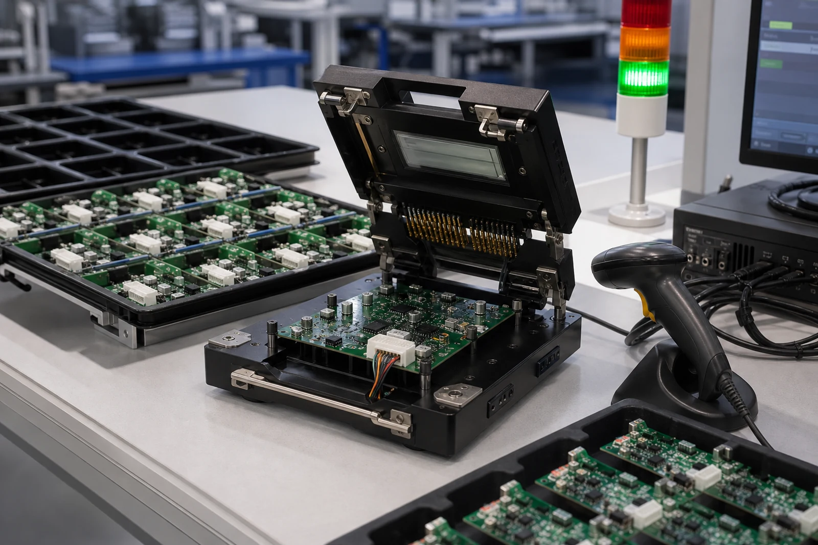
Every design passes through thermal, abuse, vibration and environmental testing, hardware-in-loop validation, production end-of-line testing, and 100K+ systems of field data feed back into the next revision.

  • Thermal testing
    THERMAL TESTING
  • Dead-short testing
    DEAD-SHORT TESTING
  • Vibration
    VIBRATION
  • Environmental cycling
    ENVIRONMENTAL CYCLING
  • Hardware-in-loop validation
    HARDWARE-IN-LOOP VALIDATION
  • Production end-of-line testing
    PRODUCTION END-OF-LINE TESTING

SOFTWARE + DATA

Edge decisions in milliseconds.
Fleet insight over millions of events.

Firmware makes protection decisions at the edge. System health streams to the cloud, where fault detection and trend analysis run today, with predictive-maintenance models in development for BESS.

Bring us the operating envelope.

Voltage. Current. Packaging. Thermal constraints. Communication. Certification. Deployment volume.